12 Results
View results:
Sort by:

For a quick overview of the cross‑sections used, you can show the members in color sorted by cross‑section. Use the right mouse button in the work window to select "Colors in Graphics According to" → "Cross -Sections" from the shortcut menu. In the current program versions, you can use a panel with an editable color scale for this.

Supports can be copied and moved using drag & drop, even if the "Move/Copy" function is not available in the shortcut menu. This applies to all kinds of supports: nodal supports, line supports, and surface supports. These can easily be assigned to further nodes, lines, or surfaces.
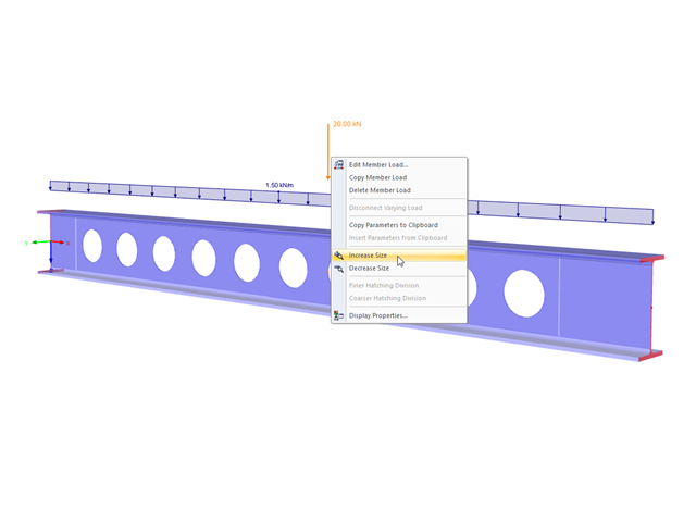
The display size of the load vectors can be adjusted quickly in the load shortcut menu: Right-click the load icon and select "Increase Display Size" or "Reduce Display Size" from the menu.
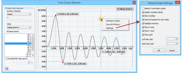
The Time Course Monitor displays the results of a time history analysis from RF‑/DYNAM Pro – Forced Vibrations. The graphic can be adjusted in the settings. This can be reached by right-clicking in the shortcut menu. For example, you can activate or deactivate the grid in the graphic. Those changes are overtaken into the printout report when you print the graphic.
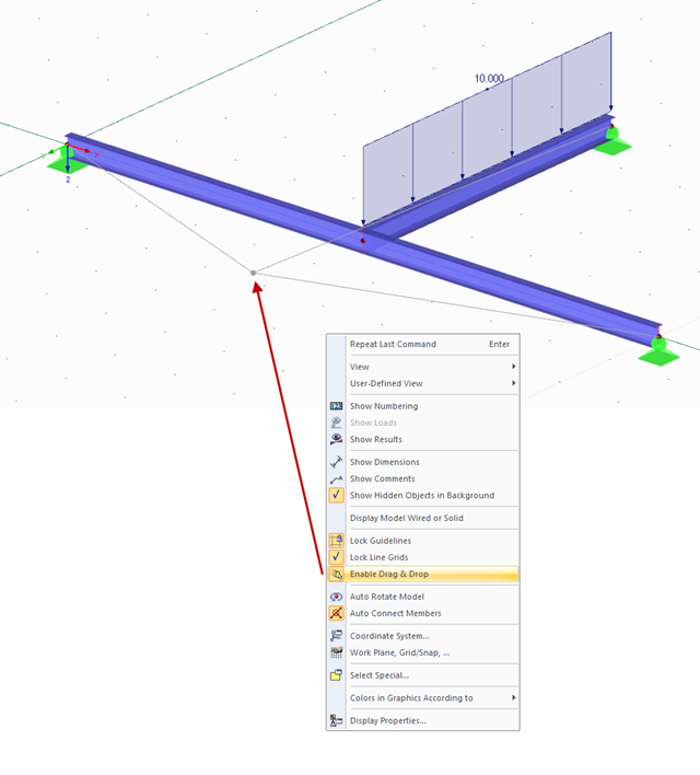
You can move and copy objects directly in the display window in order to work more efficiently. If this feature is not desired by the user, you can simply disable it. To do this, right‑click in the display window and select the "Enable Drag & Drop" entry in the shortcut menu.
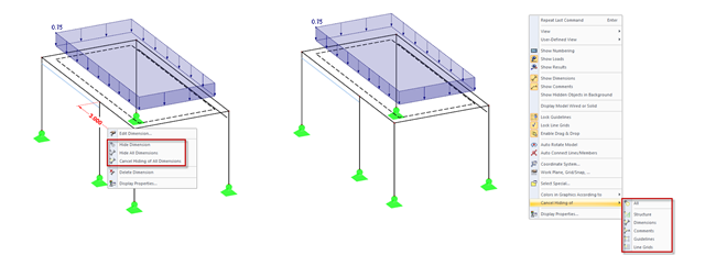
In addition to the options of Project Navigator - Display, you can modify the visibility of structures (members, surfaces, and so on) and guide objects (dimensions, comments, guidelines, and so on) in the menu and toolbar using the shortcut menus.
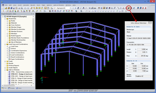
You may already be familiar with the "Center of Gravity and Info" function, which can be accessed using the shortcut menu of any element. If you want to display this information on several elements consecutively, you have to close the dialog box and open the shortcut menu of the next element over and over again.
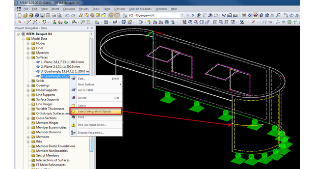
Generally, RFEM automatically detects all objects lying on a surface that are not used for surface definition. Objects integrated into surfaces can be selected using the "Select Integrated Objects" option in the shortcut menu of the relevant surface in Project Navigator. This way, you can easily find in the graphics which objects have already been integrated into a surface, for example.
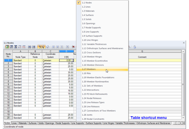
The geometry data of an RFEM model are currently managed in 29 tables, so not all of the tabs are displayed at once. To open a particular table, we recommend using the navigation menu that you can open by right-clicking on any tab. A shortcut menu appears, where you can quickly access the desired input table.
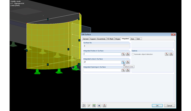
RFEM facilitates modeling by the automatic integration of objects into surfaces. However, it is impossible to integrate the objects automatically in the case of curved surfaces. For manual integration, select the relevant surfaces and click the "Edit Surfaces" option in the shortcut menu; then, in the "Integrated" tab, you can integrate the relevant objects using the "Select" function. This way, you can avoid error messages caused by non‑integrated objects when starting the calculation.
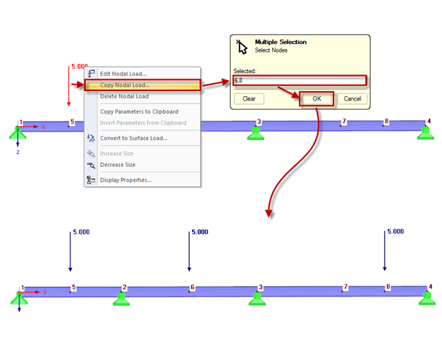
You can quickly copy nodal loads to other nodes using the "Copy Nodal Load" option in the shortcut menu. To do this, select the nodal loads to be copied first, then click the "Copy Nodal Load" option in the shortcut menu. A "Multiple Selection" window appears where you can enter the relevant nodes to which the nodal load is to be copied. After clicking "OK" to close the window, the nodal load is copied.
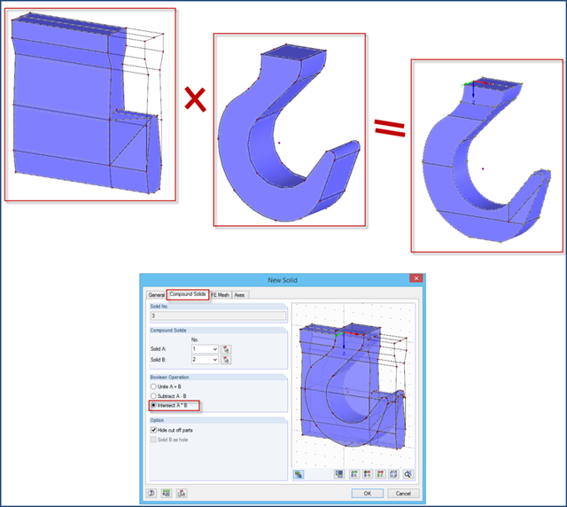
The "Intersect" option may facilitate the modeling of complex solids. This option is available in the shortcut menu after selecting two solids.